
Aluminum Corner Connector Machining and Fit Inspection
Qualify connector locating faces, hole positions and assembled corner fit using the actual frame sections.
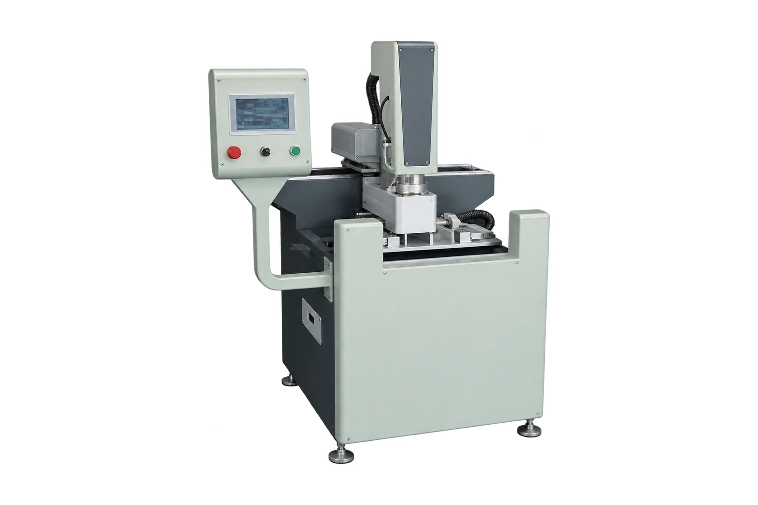
Work backwards from the frame chambers
Give the machine supplier the connector drawing and both mating frame profiles. Mark the insertion depth, handed features and the surface that locates the connector in the frame. A hole pattern measured from the wrong outer face can pass a loose check yet misalign after insertion.
Qualify the locating and machining sequence
Use an approved stop and clamp drawing for the connector blank. Inspect one part before and after reloading to distinguish a programming error from seating variation. Check diameter or slot size separately from the distance between features. Look for burrs on insertion faces and around fastener openings.
Assemble the actual corner
Fit the connector to a pair of production mitres and verify it seats before installing the prescribed fasteners. Confirm that the screw paths and frame faces align. If the fit changes after deburring, record where the burr formed and include that edge in the inspection sheet. Repeat using the shortest connector and the tightest insertion chamber in the order mix.
What to record before production release
Use a simple inspection sheet with connector seating depth, hole-to-edge distance and finished frame gap on separate lines. Record the profile chamber revision. If a new extrusion lot changes the insertion fit, compare the mating chamber before modifying the connector program.
Related equipment and reading
Send your drawings or samples for review.
Technical reference
Fom Industrie FMC technical sheet. An industry example of documenting working areas, stops, vices and tool configuration independently. It does not specify Jinren capability.