
Aluminum Door Handle Slot and Spindle Alignment
Check handle slot milling as a system with the lock spindle, fixing holes and escutcheon.
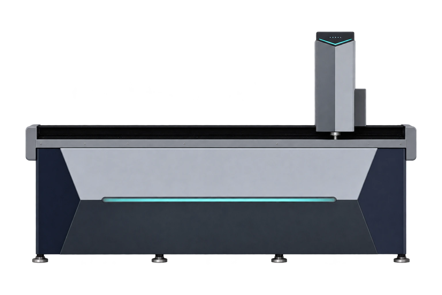
Locate from the same door reference
Record the lock backset, spindle axis and screw spacing on the same finished door drawing. Identify the faces from which each opening is machined. The handle slot can meet its own size tolerance while still missing the spindle axis if two setups use different origins.
Verify the assembled stack
Inspect the slot and holes for position and edge condition, then fit the lock, spindle and trim. Check that the spindle can enter freely with the lock seated, and that the fixings pull the trim flat without shifting it. If the handle binds after tightening, inspect alignment and screw interference before widening the slot.
Include production variants
Trial the deepest section and any left and right variants. Keep the same lock and trim set during the trial unless a hardware variant is itself being tested. Record the program, cutter and locating face for each part. If several hardware sets share a door section, prove each drawing revision rather than assuming they share one hole pattern.
What to record before production release
Record the spindle centerline at the two faces and mark the face used to locate the part. A loose fit with the trim removed and binding after tightening points to a different investigation than a spindle that cannot enter the lock at all.
Related equipment and reading
- Automatic Tool Change Hinge Milling Machine
- CNC Milling Lock Pockets and Concealed Hinges in Aluminum Doors
Send your drawings or samples for review.
Technical reference
Fom Industrie FMC technical sheet. An industry example of documenting working areas, stops, vices and tool configuration independently. It does not specify Jinren capability.