
Aluminum Profile Notching Near a Joint
Define the clearance that a notch must create and the material that must remain for the connector or joint.
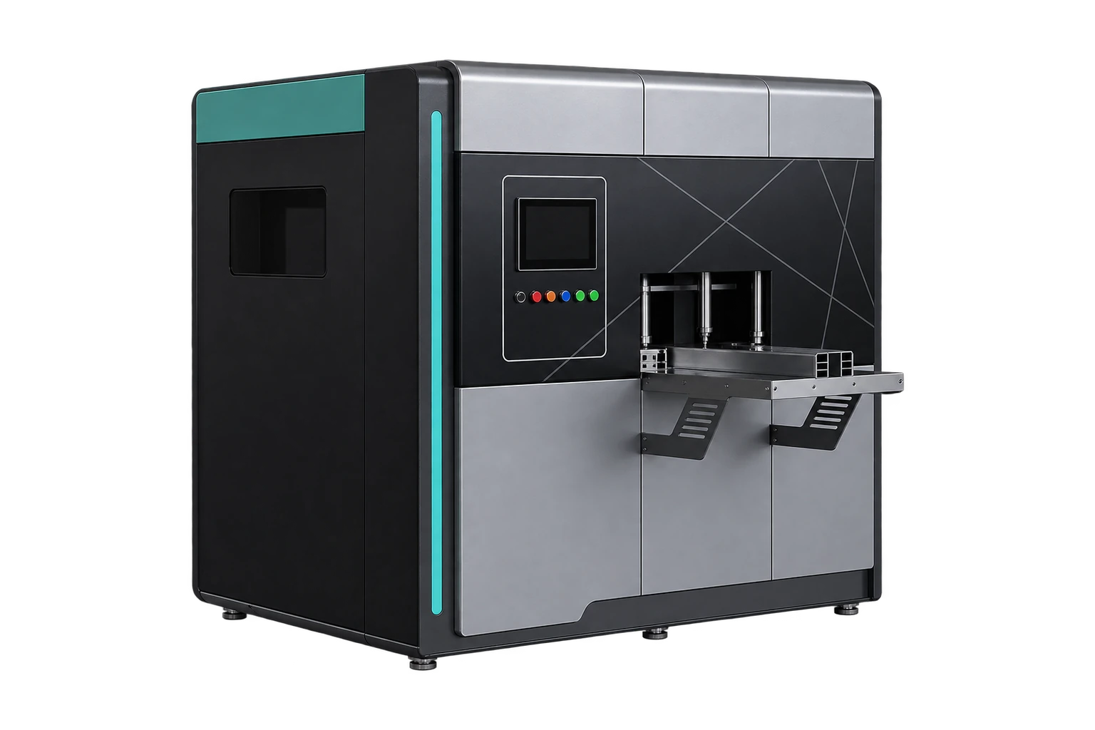
Draw the notch in the assembled position
An aluminum profile notching machine creates a local relief. Give the operator the mating section and an assembly view, not just a rectangle showing material to remove. Mark the contact shoulder, fastener path and any web needed to carry or locate the connection. The profile designer should approve features near thermal breaks and structural sections.
Separate depth, position and orientation
Check notch depth from a stated reference, then measure its shoulder from the finished end. A notch can have the right depth and still sit too far toward the face. Use a labelled left and right sample where the machining is handed. Check whether burrs are hiding a contact problem before altering offsets.
Confirm with the actual fitting
Trial-fit the mating profile and connector without forcing the parts. If the joint binds, mark the first point of contact and compare it to the drawing. If it rocks, check the retained bearing faces and the location of the stop. Inspect a second part after reloading and retain the approved sample so later batches can be checked against the same condition.
What to record before production release
For a handoff sample, mark the preserved shoulder on the approved part. Pair it with a rejected sample showing where fit was obstructed, if available. Operators can then distinguish a stop-position problem from an incomplete relief during first-piece inspection.
Related equipment and reading
Send your drawings or samples for review.
Technical reference
Fom Industrie MISTRAL technical sheet. An example of separate angle, profile-stop, vice and cutter specifications.