
How to End Mill Aluminum Window Transoms
Set up and inspect aluminum window transom end milling using mating profiles, cutter clearance, joint fit and a repeatable first-piece trial.
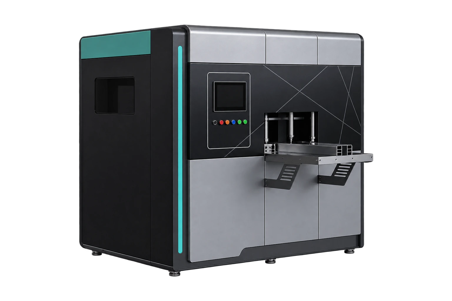
What should an end-milled transom actually fit?
End milling shapes the end of a horizontal aluminum transom so it clears and seats against the mating vertical frame profile. Start with the section drawing of the assembled joint, the connector drawing, and one piece of each production extrusion. A cut-list length tells you where the member ends. The joint drawing tells you which steps, flanges and chambers need relief and which faces must remain intact.
This guide covers a typical mechanically joined aluminum window transom. Use the profile system supplier's approved joint drawings and fastening details for your system. The workflow below is a proposed sample trial, with no implied universal tolerances or Jinren performance claims.
1. Turn the joint drawing into a machining brief
Lay out the transom and the mating frame in their installed orientation. Label the visible face, the mating end and the datum face. Trace the profile at both ends of the transom, because a joint that looks symmetric in elevation can have different relief on the left and right. Mark the bearing surfaces and identify which flanges or webs must remain to support the connector or retain a seal. If the extrusion includes a thermal break, ask the system supplier to confirm any machining close to the insulating strip.
| Information to mark | What the machine supplier needs to demonstrate |
|---|---|
| Finished length and its reference faces | Where the workpiece touches the end stop, and how the drawing dimension is measured after machining. |
| Joint contour and relief depths | That the cutter reaches each required step without cutting into a bearing face or protected section. |
| Handing and visible finish | How the operator distinguishes left and right ends and protects the finished surface against clamp marks. |
| Connector and fastening details | That the specified connector seats fully and fixing holes align when the assembly is fitted. |
2. Choose tooling by contour and batch mix
For a stable profile family with repeat orders, ask whether a dedicated cutter or cutter stack can produce the joint contour with fewer setup adjustments. For frequent changes in contour or angle, evaluate how a programmable or adjustable end milling machine handles the transitions. Compare the tooling required for each profile, time to change and verify a setup, and whether the operator can recall the correct stop positions or program revision. Include the actual cutter and holder in the quotation.
Published machines show why these checks matter. The elumatec AF 222/02 lists table height adjustment, horizontal and vertical clamping, and several depth-stop positions. Fom's MISTRAL 200 technical sheet documents a variable-angle arrangement and a height-adjustable profile stop. These are examples of different ways to position a profile for end milling. Confirm the usable angle range and cutter access on your extrusion before treating any catalogue value as a production limit.
3. Set up and verify the first piece
- Cut the blank to the drawing reference. Verify its starting length and orientation. An incorrectly sized blank can produce a neat end contour and still leave a gap in the frame.
- Locate before clamping. Seat the extrusion against the approved stop and support it so it cannot rock. Review the jaws and cutter path with the actual extrusion installed. Use the machine maker's operating and guarding procedure for setup and machining.
- Check both ends against the joint drawing. Inspect relief depth and shoulder position from the nominated datum. Deburr according to the approved process, then check for marks on visible faces and interference near the connector.
- Dry-fit a complete joint. Fit the specified connector and mating extrusion. Check seating, alignment and the gap at the visible joint against your drawing. Repeat after unloading and reloading another blank to catch stop or clamping variation.
Why does a transom still show a gap after machining?
Start by separating blank-length error from contour error. Check the length using the same references as the cut list. If length is correct, use the mating extrusion to identify the first point of contact. A burr, uncut flange, reversed setup or misplaced shoulder can keep the joint from seating. If the sample fits only when forced, inspect the geometry and connector alignment before changing the machine offsets. If the first part fits but later parts drift, check for chips at the stop, inconsistent seating and movement during clamping.
What to send for a Jinren sample review
Send a transom drawing, the mating section, connector details, two handed examples if applicable, and your expected batch mix. Ask for a trial with your widest section and your most difficult joint angle. Jinren lists a 3+1 axis CNC end milling machine in its equipment catalogue. Confirm the tooling, fixture and supported machining envelope for your project. If the same members need drainage slots or fixing holes, see the comparison of end milling and face machining before deciding whether to combine operations.
Send your joint drawings for a sample review.
Technical references
- elumatec AF 222/02 manufacturer specifications for stops, table adjustment and clamping.
- Fom Industrie MISTRAL 200 technical sheet for variable-angle end milling and profile positioning.
Use the assembled joint to judge aluminum window profile end milling. Measure the visible shoulder gap after the mating member is fully seated, and note which face was used to locate the part.