
CNC Glazing Bead Cutting and Dry-Fit Inspection
Measure the bead from the glazing system drawing, cut a complete set, and check engagement and mitre fit with the specified gasket.
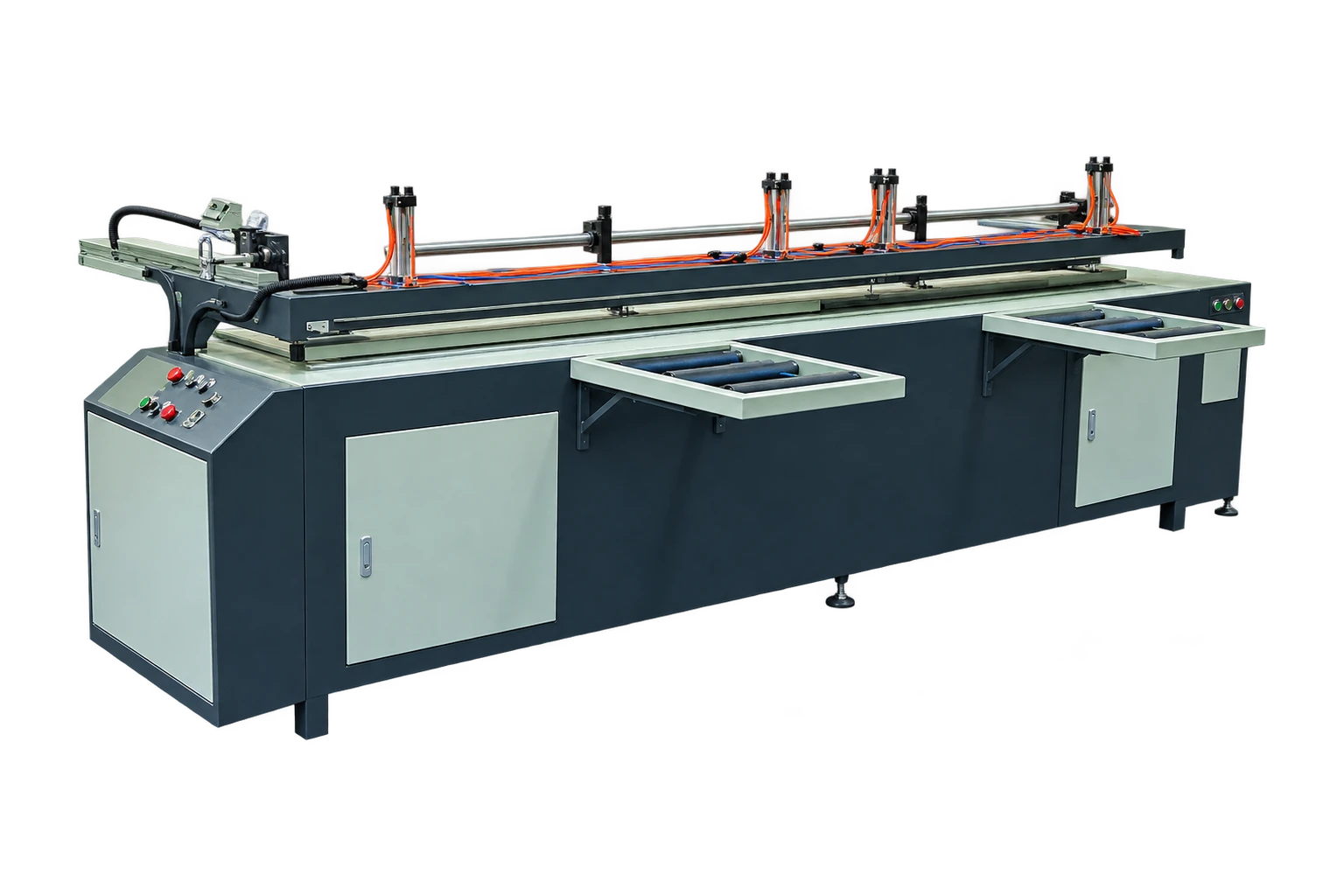
Start with the glazing pocket
Use the actual frame, glass or approved trial panel, gasket and bead section. Mark the face visible after installation and identify the locating rib. The bead cut list can differ from the outer frame cut list. A nominal glass dimension does not tell the operator where the bead tips should meet. Mark each measuring point on the assembly drawing.
Set up the shortest and longest beads
Ask the supplier to demonstrate seating and support with the same finish used in production. Verify where the stop contacts the extrusion and whether handed cuts require different loading. After cutting, inspect the engagement rib for damage and check whether a burr prevents full seating. Identify each bead before removing it from the station so opposite ends are not exchanged at assembly.
Accept a full perimeter
Install the four beads in the order specified by the glazing system supplier. Check the corner gaps, gasket continuity and visible surface marks. If an end looks short only after installation, confirm the rib is fully engaged before adjusting cut length. Repeat after a changeover and retain one labelled accepted set with its cut-list revision.
What to record before production release
Keep a bead inspection card with four labelled members, the installed viewing face and a photograph of each corner. Record which end needed adjustment and whether the correction changed fit around the gasket. This makes a second production batch easier to compare.
Related equipment and reading
Send your drawings or samples for review.
Technical reference
elumatec DG 104 technical sheet. An industry example of how a saw supplier documents angle ranges, cutting diagrams and supports. The DG 104 is not the Jinren machine discussed here.