
How to Verify a 45-Degree Aluminum Frame Cut
Verify a 45-degree aluminum profile cut using long-point dimensions, repeat cuts, corner gaps and an assembled frame check.
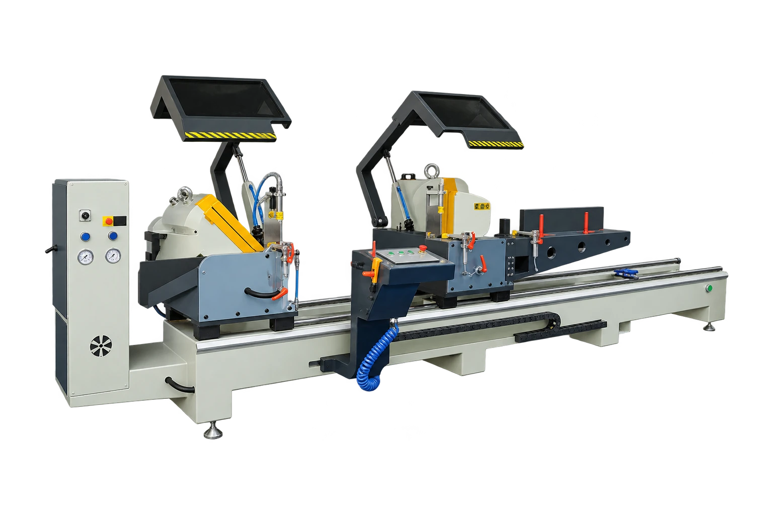
How do you verify a 45-degree aluminum frame cut?
Check three things in order: the individual cut angle, the finished member length at the drawing's specified reference, and the fit of a complete dry-assembled frame. A saw display reading 45 degrees confirms the commanded setting. The cut surface and the assembled parts tell you whether the production process delivered the joint on the drawing.
This procedure is for flat mitred corners in aluminum window and door frames. A compound mitre or a proprietary frame joint may have a different inspection sequence. Use the profile system drawing and the agreed project tolerances.
1. Agree on what the length dimension measures
Mark the long points and short points on the finished drawing and label which pair the cut list uses. Hand the same marked drawing to the operator and inspector. Identify the retained part and the face that seats against the fence. An asymmetric profile can look nearly identical when turned over, but its decorative face and the measurement line may then sit on the wrong side.
In an ideal flat 45-degree cut, the longitudinal distance from the long point to the short point equals the projected width between those two reference edges. For example, if those edges are 40 mm apart, the two points differ by 40 mm along the length at that end. A symmetrical member with opposite 45-degree mitres would therefore have an 80 mm difference between its outside and inside dimensions. This is a geometry example, not an allowance to enter for a particular window system. Rebates, sloped faces and drawing-specific datums can change the edges being measured.
2. Verify the cut before moving the machine offsets
- Use the actual extrusion and surface finish. Check it seats flat and consistently against the approved supports and fence. Review head and clamp clearance at the working angle using the machine's cutting diagram.
- Cut a left and a right sample using the manufacturer's operating and guarding procedure. Mark them before removing them from the station.
- After the approved deburring step, check the angle against a known reference on the correct face. Measure finished length using the drawing's long-point or short-point convention. Check the face for burrs, steps and clamp marks.
- Repeat after unloading and reloading, then again after an angle or profile changeover. Record the side, section code, support setup and measured values so a recurring pattern can be isolated.
3. Read the gap pattern on the assembled frame
| What you see | What to check first |
|---|---|
| Gap opens toward one edge of the mitre | Check the individual cut angles, burrs and seating surfaces. Inspect both mating pieces before adjusting either head. |
| Corner closes evenly but overall width is wrong | Recheck the reference points used in the cut list, the controller and the finished measurement. |
| Diagonals differ although member lengths pass | Check the assembly jig, connector seating and opposite-member alignment. Measure again with the frame resting on the approved assembly surface. |
| First frame passes but later frames drift | Review repeat seating, chips at the stops, profile support and the changeover record before changing offsets. |
Use the specified corner connectors and compare both diagonals and the visible corner gaps on the same assembly. Equal diagonals are a useful check, but the frame must also meet width, height and joint requirements. Capture the readings together so the supplier can reproduce the result.
What to ask the saw supplier to demonstrate
Send the shortest member, widest section and one complete frame cut list with the length references marked. Ask to see the supported 45-degree cutting envelope and the measurement convention in the controller. The elumatec DG 104 technical sheet is an example of a manufacturer publishing a cutting diagram alongside angle and support information. Emmegi's Precision TS2 page separately lists internal and external inclination, illustrating why buyers should check which direction and reference a stated angle describes.
For a Jinren trial, review the outward-swing double-head saw and bring a complete cut list rather than a single straight sample. If you are still comparing head arrangements, see the outward versus inward double-head saw guide. Send your frame drawings for a trial review.
Manufacturer references
- elumatec DG 104 technical sheet for the cutting diagram and machine-specific support options.
- Emmegi Precision TS2 technical data for internal and external angle terminology.