
Single-Head vs. Double-Head Corner Connector Machining
Compare connector machines on the number of fixtures, reorientations and accepted parts per batch.
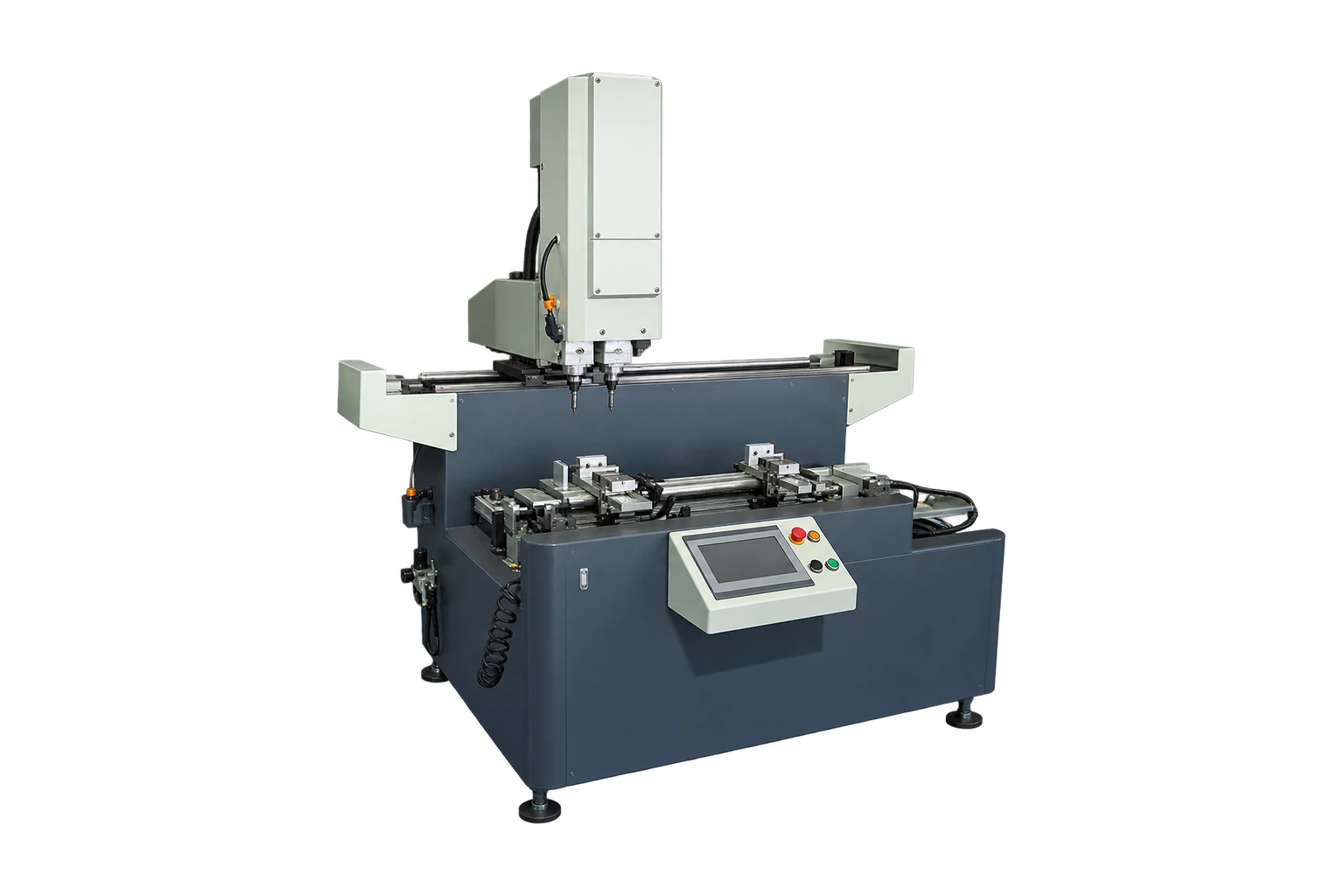
Map the faces before counting heads
Label each drilled or milled feature by its face and datum. Ask both suppliers to show exactly where the part is loaded and when it is reoriented. A double-head setup can only remove handling if its second head can reach an operation that your drawings require. Verify the head sequence and fixture access in the quoted configuration.
Test both a repeated order and a short mixed order
Record setup, first-piece inspection, load and unload time, any flip and the time spent waiting for tool changes. Count only accepted connectors at the end of the batch. For short orders, an easy-to-change fixture can matter as much as repeated-cycle speed. Include the same inspection scope for both machines.
Compare feature relationships across faces
Measure the distance between face features from a common datum after any flip. Then fit the connector in the matching extrusion and verify fastener alignment. If the feature sizes pass but holes do not align in assembly, investigate how the second setup reestablishes the first datum.
What to record before production release
Record first accepted piece, accepted batch count and elapsed time for both setups. Include the time to clear chips and change jaws. Add a separate column for features that cannot be reached in the proposed configuration, even if the overall cycle looks shorter.
Related equipment and reading
- JR-2100 Double-Head Flip Corner Connector Machine
- Three-Sided Drilling and Milling for Aluminum Profiles
Send your drawings or samples for review.
Technical reference
Fom Industrie FMC technical sheet. An industry example of documenting working areas, stops, vices and tool configuration independently. It does not specify Jinren capability.