
CNC Travel vs. Workpiece Length: Reaching Both Ends of a 3.6 m Profile
Holes 80 mm from each end of a 3,600 mm part span 3,440 mm. A 3,300 mm feature envelope falls short by 140 mm.
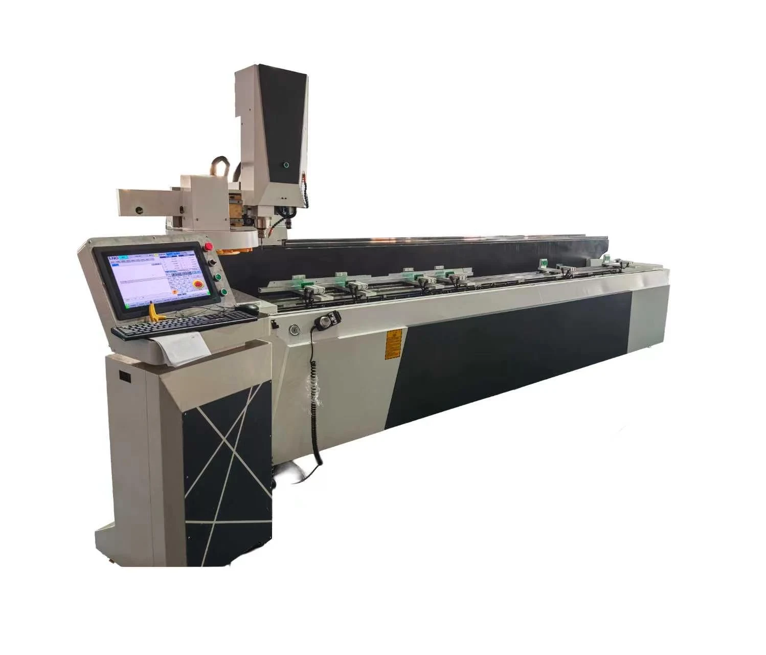
This application example uses public references and explicitly stated planning inputs. Figures derived from assumptions are estimates for evaluation, not measured customer results.
Production question
Will a 3,300 mm usable feature envelope cover holes located 80 mm from each end of a 3,600 mm profile?
Worked calculation
The hole centers lie at 80 and 3,520 mm, a 3,440 mm span. A 3,300 mm usable envelope is short by 140 mm even before any tool approach. A uniformly warmer 6063-T6 profile at +5 K would also grow approximately 0.423 mm across its full length using Hydro’s typical coefficient.
How to validate it on the shop floor
Obtain a machine travel drawing and confirm actual end reach with the intended spindle orientation, tools and clamps. If indexing is proposed, machine a witness feature and measure the change in datum after moving the part.
What to do with the result
Request an envelope check against the outermost feature coordinates, including any probe or cutter-center excursions. A shop could move the datums inward only if the drawing owner permits it. For two-position machining, keep the same physical reference surface and document how the secondary position is located. Test a feature near the handoff so that a good result at each end cannot hide an offset between setups.
Practical follow-up
Can a machine physically hold a longer profile than it can cut in one setup? Yes. Ask separately for supported stock length, available feature span and clearance for end work.
When evaluating an aluminum profile machining center, request a reach drawing for the actual spindle orientation and clamp layout.